Before removing the elevator and fuselage pieces, glue the carbon fiber strips in place. With an X-Acto
knife, remove the webs in the elevator spar slot. Spread Foam-Tac glue on the smallest flat carbon fiber strip and insert it
into the elevator slot. The medium piece goes into the precut slot of the fuselage. (the longest piece will be the
wing spar)
Remove the wing parts from the foam sheets gently with an X-Acto blade around the edges where they are attached to
the sheets and place them on a flat building surface. When you separate the wing pieces, keep each wing and
its aileron together as a set.
|

|
Bevel both the aileron and wing control surfaces being careful to make left and right ailerons match the surface
on the wings. Again, lay the top painted surface face up on the table through this process. You want to cut the foam to a
point. Place a cork backed metal ruler on top of the wing the same
distance from the edge as the thickness of the foam. Using a new X-Acto blade or snap knife, trim along the
edge/ruler at a 45 degree angle the length of the edge. If the foam starts to drag and rip, change to a new
blade.
|

|
Continue cutting bevels, lay the stabilizer top side up (important for painted kits) with the hinge edge
slightly back from the edge of the work surface or table. Remove the elevator from the fuselage sheet and cut the
elevator in the same manner. Do not cut
the bevels in the fuselage or rudder at this time.
|
|
Our preferred method of hinging is glue hinges and that is what we will reference in these instructions. Feel
free to substitute your favorite method but you might want to do a test hinge with some of the EPP scraps in
the kit to see the benefits. Check out this YouTube video to see how easy it is to make the glue hinge.
http://www.youtube.com/watch?v=q0uK8KlR-0I Holding the
two pieces to be hinged together with the top paint outward, smear a thin coating of Foam-Tac glue on
the points of the bevels you have just cut. Start with the elevator and stabilizer. The hinge is best when just
a fine coating of glue is used and the glue overlaps the point of the bevel about 1/8" on either side. With the
stab and elevator coated, let them dry to the touch. Place the stab and elevator on the building surface with
the hinge bevel points on the top (top paint up) and slide the two pieces into contact. "Squish" them together
gently, but firmly. Flex the hinge to make sure it moves freely. This joint will strengthen overnight. Continue
with the hinging of the ailerons.
|

|
Once all the elevator and ailerons have been hinged, it is time to do the main wing assembly. Working in an area large
enough that the entire outline of the wings can lay flat, take the two wing panels and test fit them making note
of the surfaces that make contact and spread Foam-Tac glue on both sides thinly and let it get tacky. Slide the
wings together top paint up and press firmly together on the flat surface so they align and attach.
You may find putting the wing carbon unglued in the slot helps alignment.
|

|
Spread Foam-Tac glue on both sides of the longest carbon fiber strip, insert it into the wing slot from the bottom.
Doing this will avoid smearing excess glue on the top painted surface.
|

|
Remove the fuselage and rudder from the fuselage sheet now. You want the rudder bevel
to be on the side that has the elevator horn slot. This will put the rudder horn on the
opposite side of the fuselage. Cut the fuselage tail bevel and then cut the same bevel in the mating rudder surface.
|

|
Take the elevator/stab subassemply and test fit it into the slot at the tail of the fuselage. You will have to spread
the fuselage slit apart to get the elevator/stab into position. Notice the stab has a small notch which stradles the fuselage
at the front. The hingeline should align with the elevator cutout in the fuselage. Remove the elevator/stab and smear
glue on the mating surfaces and reinstall it. Glue the top/bottom of the fuselage slit together. Use one of the vertical
guides to hold the elevator/stab at a 90 degree angle to the fuselage. I generally pin through the edges of this guide
into the elevator/stab to hold it in place. Glue the rudder hinge in place at this time.
|

|
Take the wing/aileron subassembly and fit it into the wing slot in the fuselage in the same manner as the elevator/stab.
Use the second vertical guide to align the wing.
|

|
Find the black stick motor mount in the parts bag and assemble the nut and bolt into the hole at the bottom. The notch
with the nut and bolt is the bottom of the mount. Sand the top and bottom surface of the mount to allow the glue to
grab better. Smear glue on this top and bottom surface and glue the mount into the front slot of the fuselage and set the
plane aside to dry. Take care to glue this straight in the slat as this determines your thrust line and must be parallel to
the fuselage sides.
|

|
Take the straight nylon servo arm and position/align it into the plywood aileron servo bellcrank (bowtie shaped) concentric
with the screw hole. If you are using the 9 gram servo included in our completer kit you will find alignment holes in the
bellcrank that the two mounting screws in the servo hardware can be used to secure it. We have cut the center hole to be snug
on the servo arm and attach under the arm.
|

|
The elevator horn has a notch in it to step over the elevator spar and is different from the other horns. Install
it into the bottom of the elevator. Smear Foam-Tac glue on both sides of the glue lines on the tab and insert it
into the precut slot. Insert the aileron control horns into the precut slots in the bottom of the ailerons so they
are flush with the top of the aileron slot and the holes are aligned over the hinge line. Glue the rudder horn into
the rudder in a similar manner.
|

|
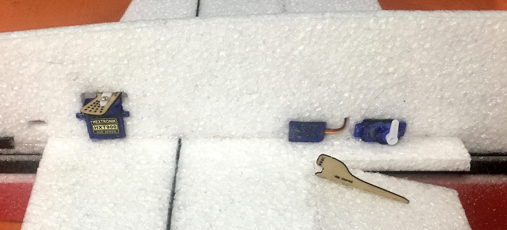
With the aileron servo bellcrank mounted as shown, install the 9 gram aileron servo in the precut hole in the
front of the plane. Note that the servo output shaft is towards the rear as is the flat side of the bellcrank.
Tack glue the servo in place with your preferred method, I use Foam-Tac glue on the mounting ears but other
people use low temperature hot glue.
|


|
Install the 5 gram tail servos in the precut holes below the wing. Note that the servo output shaft is towards
the rear and on opposite sides of the fuselage and on the same side as the control horn, the elevator servo is
in the more forward position. Glue the servos in place with your preferred method, I use Foam-Tac glue on the
mounting ears but other people use low temperature hot glue.
|

|
Install the motor into the stick mount and tighten the screw. Hook up the ESC and servos to the receiver and
check the motor for the proper direction. Reverse any two wires to the motor if it is backwards.
|

|
Measure the carbon fiber pushrods to be 1/2" smaller than the distance from
the servo arm screw to the surface hinge line at the control horn as shown in the pictures.
|


|
Attach the Z-bend wires to each end of the carbon fiber pushrods using the
small pieces of heatshrink tubing. Note that for the tail pushrods, be sure to slip the pushrod guides/stand
offs on the rods before doing the second end. ***DO NOT GLUE AT THIS TIME***
|

|
Install the pushrod z-bends into the aileron horns and then with the bellcrank loose, insert the z-bend ends into the
outer hole, second from the front lobes. Pop the bellcrank back onto the servo and center it and adjust the ailerons
so they are level. The rods/z-bends will slip under the heat shrink tubing to allow this adjustment but also hold it
in place for gluing. Glue the z-bend wires to the carbon fiber rods with CA to hold this position. Do this same
procedure for the rudder and elevator pushrods while being careful not to let any CA run down the pushrod and glue
the pushrod support to it. Then poke (and then glue) the pushrod supports into the fuselage at equal distances along
the pushrod length.
|


|
The airframe is now completely assembled.
Using Velcro, attach the receiver and ESC to the fuselage and clean up the wires. With
the servos electronically centered, install the servo arm screws in all the servos.
Put a long strip of Velcro on the opposite side of the fuselage from the receiver/ESC in order be able to move the
battery forward and back to fine tune your balance. Due to the electronics being mounted under the wing, placing the
battery above the wing helps make the rolls more axial. The Velcro will stick best to the EPP if you rub some Foam-Tac
on the area you are attaching it to. The initial CG of the plane is on the carbon wing spar to 1/4" behind it.
Move the battery forward and back on the velcro strip to try different positions to find your preference.
Control throws are a matter of personal preference. Some people want lots of surface movement to do 3D maneuvers
while other people like a more docile handling plane. The Superslo28 responds very well to rudder movement and throws
up to 45 degrees in each direction are often used. You can add exponential to your controls to calm down the center
portion of the travel. If you are going to go for this type of aggressive throws, you might want to start with 50%
exponential until you get a feel for the plane. EPP is very durable and also easily repaired. Don't be afraid to
challenge yourself and learn new things. Get out and enjoy flying.
|