Flat Foamie Series
40" EPP Extra XL Build Instructions
| This version dated July 8, 2021 The Latest Version is Available Online at http://www.racores.com/FlatFoamieExtraXLInstructions.html (click on the pictures to expand) We suggest that you read through the instructions once before you start building to become familiar with the sequence of steps and the flow of construction. Do not remove the parts from the sheets before instructed. Some steps are done with the parts in the sheets. |
|


|
|
Kit contents as it comes out of the box


Remove this page from the instructions and refer to the diagrams on the back (Page 2) to locate the parts as you build.

Kit Contents as it comes out of the box.

Please note, the order of these steps is such that subassemblies will dry while you do the following steps in preparation for their use. Do not remove the parts from the sheets before instructed. Some steps are done with the parts in the sheets.
- Remove the front wing KF bottom pieces (D1 and D2) from the sheet, glue them at the center with Foam-Tac and
set aside to dry.
- Leaving the parts in sheet F, glue the 333mm piece of flat carbon fiber into the slot in the elevator (F2) with
Foam-Tac and set aside to dry.
- Find the ailerons (C3 and E3) and remove them from the sheets leaving the other parts in the sheets. Remove the
L shaped scrap foam piece from the aileron position against the rear wing pieces (C2 and E2). Bevel this exposed edge of
the rear wing pieces (C2 and E2) from the bottom using a new sharp blade and the cork-backed ruler supported by
the surrounding foam (C1 and E1). Bevel the corresponding edge of the ailerons (C3 and E3). With the bevels cut,
remove parts (C2 and E2) from the sheet. Using a fine bead of Foam-Tac, hinge the ailerons to the rear of the wing.
Use less glue for the hinge than you think you need as it will stiffen over the first 24 hours. You can always
smear additional glue on the hinge at a later point. Repeat for the second wing half.
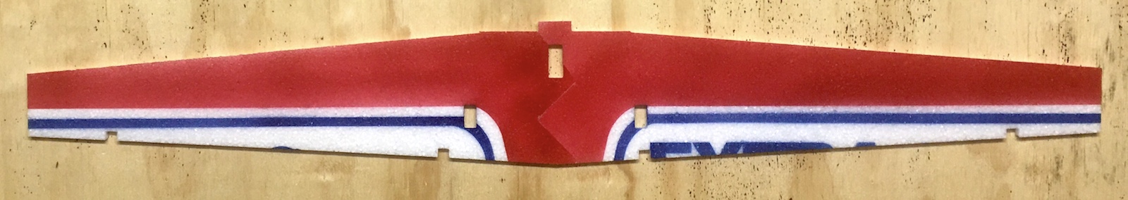
- Glue the two wing halves (C2+C3 E2+E3) together at the center section and set aside to dry.
- Remove the front wing KF top pieces (C1 and E1) from the sheets and glue them together at the center and set
aside to dry.
- Making sure the center joint is dry, glue the 750mm piece of flat carbon fiber into the slot in the
front wing KF bottom pieces (D1 and D2) subassembly and set aside to dry.
- Remove the Fuselage Top Front (A3) and Rear (A1) parts and glue them together. The joints are asymmetrical
and the pieces need to flip over so they match each other. Do the same with the Fuselage Bottom Front (B1)
and Rear (B2) and set aside to dry.
- From Sheet F, remove the Horizontal Stabilizer (F1), and the scrap foam from the front of the Elevator (F2).
Using the trapezoidal scrap of foam as a resting point for the cork backed ruler, bevel the Elevator (F2)
hinge on the bottom (the spar should make this process easier).
- Bevel the rear edge of the Horizontal Stabilizer (F1). You can now remove the Elevator (F2) from the sheet and
hinge it with the Horizontal Stabilizer (F1) using a fine bead of Foam-Tac. Glue the small end of the Rear Horizontal
Fuselage (F5) to the tab on the front of the Horizontal Stabilizer (F1), making sure the paint side is correct and
set aside to dry.
- Cut two diagonal slots on either side of the joint of the Horizontal Stabilizer (F1) and Rear Horizontal Fuselage (F5)
and glue the two 75mm carbon fiber strips into them. This will prevent the tail from skewing.
- Find the plywood sheet with the 40" XL Leading Edge Jig on it and carefully pop the pieces loose. Press the legs
into the slots so they are all facing the same way and flush with the bottom. The leading edge foam will rest on
this in the following steps.
- Remove the 4 KF Keys (F3) and glue them into the long notches on the front of the wing subassembly (parts C2, C3, E2
and E3) so the small knobs project above and below the wing subassembly.
- Place the front wing KF bottom pieces (D1 and D2) with the carbon spar in it, on the build surface paint side down and
raise the leading edge of it on the plywood Leading Edge Jig. Remove the 4 9mm Fuselage Jigs (F4) from sheet F and place
them behind the KF Bottom Pieces (D1 and D2) at equal distances across the span. These will raise the wing
subassembly off the building board to the correct height. Place the wing subassembly (bottom paint side down) and put
it on the front bottom KF, positioning the KF Keys (F3) tabs in the associated notches in the front wing KF bottom pieces
(D1 and D2). Do it initially without the glue and then apply Foam-Tac to where the pieces overlap, pressing it down to make
good contact and let dry.
- Remove the five triangular wing ribs (A5) from Sheet A and glue them into the notches and onto the inside of
the front wing KF bottom pieces (D1 and D2), paying attention that the longest one goes in the center and the
two shortest ones are even with the wingtips.
- Spread glue on the inner surface of the wing assembly (from the above step) along the leading edge, across the
top of the ribs, and across the front of the wing rear pieces. Put the front wing KF top pieces (C1 and
E1) subassembly, paint side up, on the glue and align the leading edge, wing tips and KF Keys (F3) tabs in the
associated notches. Pin this sandwich together along the KF Step and leading edge to maintain a good glue joint.
This subassembly needs to dry well for the following steps.
- Remove the horizontal fuselage nose (A2) from Sheet A and with the paint side up (the top of the plane is
currently up) glue it to the tab on the front of the wing assembly. Supporting the nose with the 6mm fuselage
nose jig (G2), align the wing leading edge top/bottom seam in the center of this piece and let dry. Note: Make
sure that the center line of the nose (A2) matches the center line of the wing assembly. The leading edge of
the wing is 18mm thick and this nose piece is 15mm so there will be a slight step. 1.5mm of this step should
be on each side of the wing.
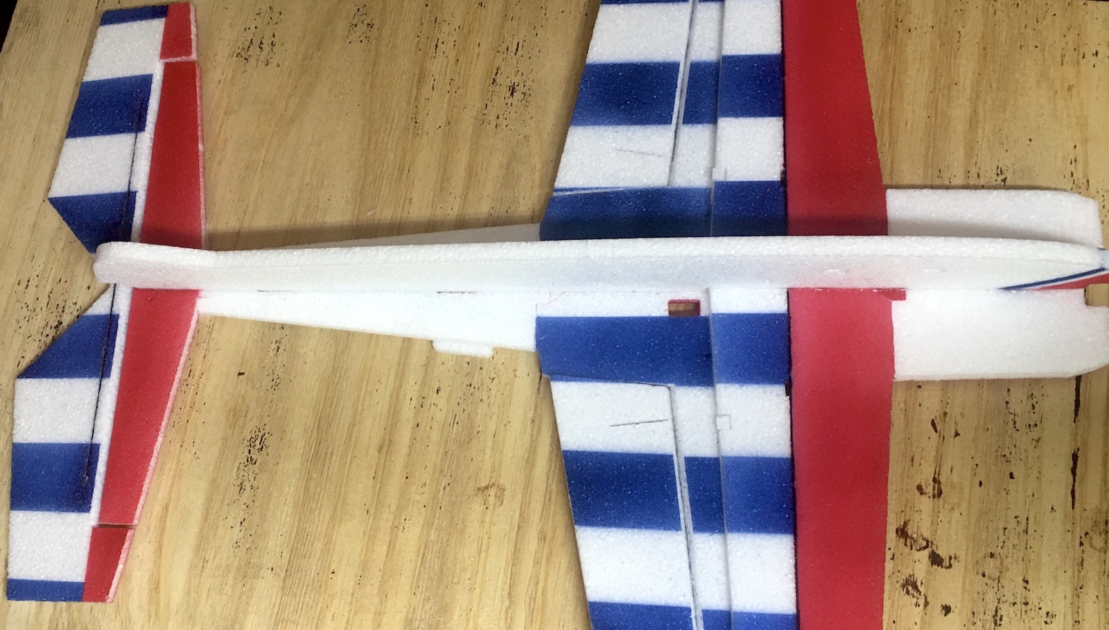
- Using the four 9mm fuselage jigs (F4), glue the Stabilizer/Elevator subassembly (F1, F2 and F3) to the notch in the
rear of the wing assembly making sure the top paint is facing up on all pieces. Support the pieces with the 9mm
fuselage jigs (F4). You now have the complete horizontal outline of the plane assembled.
- Hold the Rudder (B3) over the plane and figure out which side to cut the bevel so the point (and thus the Rudder horn)
is on the opposite side from the elevator horn slot and bevel the hinge line.
- Using the Rudder (B3) as a guide, cut the corresponding bevel at the rear of the top (A1 and A3) fuselage subassembly.
Do not hinge these pieces at this time. It is simply easier to cut the bevel now before the vertical fuselage
parts are installed.
- After allowing sufficient time for the fuselage nose and tail assembly attachments (the flat horizontal framework)
to dry, take the fuselage bottom subassembly (B1 and B2) and dry fit the tabs into the associated slots to verify
fit. The critical alignment here is the cutout for the firewall in the nose to maintain a proper thrust line. Trim
the tabs if necessary to get the proper fit. Remove from the slots and spread glue on the flat portions between the
tabs (not on the tabs at this point) and reinsert and realign it. Making sure you have a good glue fit, support the
fuselage bottom (B1 and B2) vertical with construction squares and let dry.
- From Sheet G, remove the two rear fuselage stiffeners (G1) and bevel both of the long edges.
- The two rear fuselage stiffeners (G1) are glued to the bottom of the fuselage at a 45 degree angle to form a
triangle cross-section with the fuselage bottom and horizontal outline and even with the rear fuselage bevel.
This will prevent the tail from twisting in flight, so it is important to complete this step flat on the
building board to maintain the alignment. There are small alignment holes and slightly larger ones paired in
the rear of the wing and stabilizer. You can put round toothpicks into the smaller holes to help align where
the edges of the fuselage stiffeners should go. The ends of the stiffeners should position between the larger
holes. The large end of the fuselage stiffeners (G1) should face the front/wing end. Dry fit the fuselage
stiffeners (G1) in place before spreading glue on both the beveled edges and attach one of the fuselage stiffeners
(G1) to each side of the rear fuselage.
It is important to let the glue fully dry as this is your tail alignment and the plane will be removed from the building board next step.
- With the current assembly dry, lift the plane from the building surface and lift the main assembly off the
build table and turn it upright. Dry fit the Fuselage top (A3 and A1) into the slots. The critical alignment
here is the cutout for the firewall in the nose to maintain a proper thrust line. Trim the tabs if necessary,
to get the proper fit. Spread glue along the bottom of the fuselage top, including the tabs this time, and
glue it into the slots. Align the front of the fuselage in the firewall area so the edges all match and be
sure the fuselage is perpendicular to the horizontal plane surfaces. Let this dry and check to be sure the
glue joints remain tight and vertically aligned.
- Find the two plywood firewalls and notice the grain on them. Matching the screw pattern, glue the firewalls
together so the grain is 90-degrees to each other for added strength. Spreading glue on the fuselage foam pieces,
glue the firewalls in place in the nose, being careful to align them perpendicular to the fuselage. This is your
thrust line so be sure it's aligned. I use the motor mounting screws to clamp the two firewalls in alignment
while the glue dries.
- Using a thin bead of Foam-Tac, hinge the Rudder (B3) to the rear of the fuselage.
- Find the quarter round gusset pieces (A4) and glue them in place as shown behind the firewall. This is
important as it gives the firewall more glue surface and prevents the motor breaking off as easily. Use all 8
pieces, 2 per quadrant and don't be stingy on the glue.
- Find the plywood control horn sheet and remove the 4 horns. Notice that one of them has a right-angle front on
it (bottom right in picture). This is to go up against the Elevator (F2) carbon fiber spar. I recommend you install
this one first to avoid it being installed in the wrong slot. There is also a taller one marked "Rudder Horn"
(bottom left in picture). This one is for 15mm thick foam and goes in the Rudder (B3). I find spreading glue on the
horns and squeezing some into the horn slots gives a strong attachment. The front ear of the horn should match the
hinge joint so the pushrod holes line up over the hinge for optimum geometry. Install the other 2 horns in the same
manner in the Ailerons (C3 and E3). All horns mount on the top surface (away from the bevel) with the Rudder horn
installed on the opposite side from the Elevator horn.
- If you have chosen to install our optional landing gear set, now is the best time to install the plywood
mounting plates using the pass-thru holes on the fuselage as a positioning guide. Follow the instructions
provided with the Landing Gear set. The gear struts can be put on and off in the future using the two screws
provided with the gear set.
- Install the 9g servos in the holes provided. If the wing servos don't sit flush with the top of the wing you might
need to remove some foam from inside the wing to allow it. The wing servos have the splined post towards the front
of the plane and the tail servos have the splined post towards the tail. Route the wires down to a common area where
your Rx will be located. There are pass-thru holes provided. Do not install the servo arms at this time.
- Measure and cut the pushrods to be the distance from the servo splined post screw hole to the hinge line at the horn,
minus 1/2". Keep in mind that the Rudder pushrod is longer than the Elevator one. Clean the Z-bend wires and
ends of the carbon rods with the sandpaper or alcohol to remove any possible oil.
- Assemble the pushrods with the Z-bend wires and heat shrink tubing. Do not glue the Z-bend wires at this
point.
For the tail servos, install half of the pushrod supports on each pushrod before putting the second
Z-bend in place.
- Pick a surface and install the appropriate pushrod in the control horn. Take a servo arm and install it
on the opposite end of the pushrod. With the surface held at neutral, install the servo arm on the splined
shaft so that it is at a 90-degree angle to the pushrod. The splines seldom line up perfectly so just find
the closest one. This will be adjusted using the subtrims on your radio. Slide the Z-bend wires under the
heat shrink as needed for alignment. Do not install the servo arm screw at this point. Repeat for the other
3 servos.
- Assemble the firewall mount on the motor as per the manufacturer's instructions. Bolt the motor to the firewall
(without the prop) positioning the wires so they point to the side chosen for the radio installation. Connect the
ESC and route the servo wire to the Rx area and pass the battery wire through the fuselage hole to the opposite side.
- Connect all the servos/ESC to the Rx being aware that you will need to set up dual aileron servos in the programming
(which is dependent on your choice of radio). Plug in a battery to the ESC and bind your radio to the plane. This
will also center your servos. Be sure you don't have any trim/subtrim set up at this point. Unplug the battery and
turn off the radio. Remove the bind plug from the Rx, if necessary.
- Turn the radio on again and verify the servo directions and reverse any as needed. Using the subtrim feature
for each channel, set the servo arm perfectly 90-degrees to the pushrod. Verify the control surface is set to
neutral and with a piece of paper towel protecting the paint, put CA on the Z-bend at one end of the pushrod.
Verify the surface is neutral again and CA the other end of the pushrod. On the tail pushrods be careful not
to drip any CA onto the pushrod supports. Install the servo arm screws, unplug the battery and turn off the
radio.
- Install the propeller on the motor at this time and power up the plane again. Holding the plane securely away
from yourself, give it a small amount of throttle to verify direction. If the motor is running backwards, swap
any two motor connections to the ESC and retest. Unplug the battery and turn off the radio again.
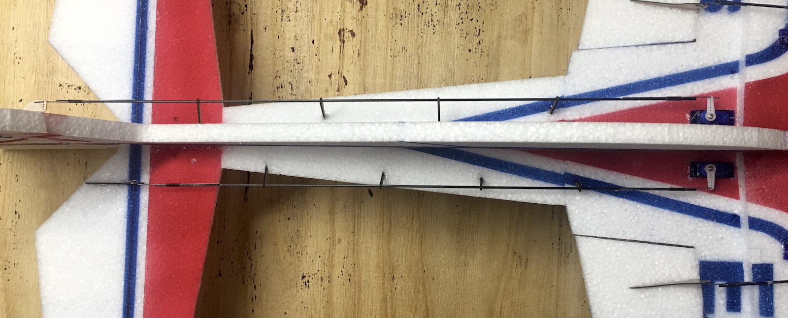
- At regular intervals on the tail pushrods, stab the pushrod supports into both the vertical and horizontal
foam and glue in place with Foam-Tac. Sight down the pushrods to make sure there are no bends or kinks to cause
binding. Make sure the supports are perpendicular to the pushrods to avoid binding.
- Attach the Rx and ESC to the fuselage using Velcro. Using cable ties, gather up the excess servo leads to
neaten the installation. You can see I was able to hide the excess servo leads under the rear fuselage stiffeners
(G1). I like to have all the components on one side of the fuselage and then use a long piece of Velcro on the
other side for battery attachment. This allows you to position the battery forward or back to fine tune your CG.
Slightly tail heavy will hover a little better for example.
- Initial CG should be set to approximately the wing spar position (where the color changes) and then adjusted
through flight testing to your personal preference.
|
|
|
|
|

|
|
|

|
|
|

|
|
|

|
|
|
|
|
|

|
|
|

|
|
|

|
|
|

|
|
|
Picture coming soon. |
|
|

|
|
|

|
|
|

|
|
|

|
|
|

|
|
|

|
|
|

|
|
|

|
|
|

|
|
|
|
|
|

|
|
|

|
|
|
|
|
|

|
|
|

|
|
|

|
|
|

|
|
|

|
|
|

|
|
|

|
|
|

|
|
|

|
|
|

|
|
|

|
|
|

|
|
|

|
|
|

|
|
|
|
|
|

|
|
|
|