Flat
Foamie Series
EPP Spitfire Build Instructions

The Latest Version is Available Online at http://www.racores.com/FlatFoamieSpitfireInstructions.htm
(click on the pictures to expand)
We suggest that you read through the instructions
once before starting building to become familiar with the sequence of steps and
the flow of construction
|
|
Items required to build the plane: A Hobby Knife and replacement blades or Snap
Knife A cork backed metal ruler, 18” recommended CA Glue (regular or foam safe) and kicker EPP Contact Glue (Foam-Tac, UHU por or Welders) A piece of fine sandpaper to roughen the pushrod
pieces for gluing Optional: four .032” EZ-Connectors for your pushrod attachments |

|
|

1.
 Remove the parts from the foam sheets gently with an
X-Acto blade around the edges where they are attached to the sheets and place
them on a flat building surface. When you separate the wing pieces, keep the
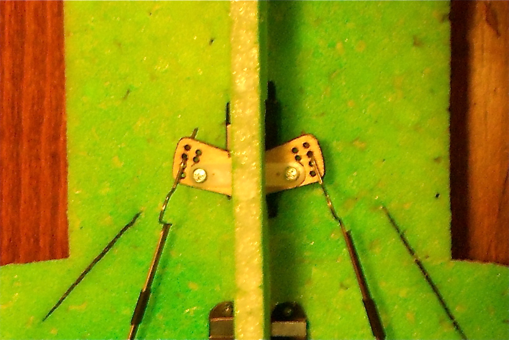
wings and ailerons together as pairs.
Remove the parts from the foam sheets gently with an
X-Acto blade around the edges where they are attached to the sheets and place
them on a flat building surface. When you separate the wing pieces, keep the
wings and ailerons together as pairs.
2.
 Bevel both pieces of all the hinge joints. Lay the
stabilizer top side down (important for painted kits) with the hinge edge
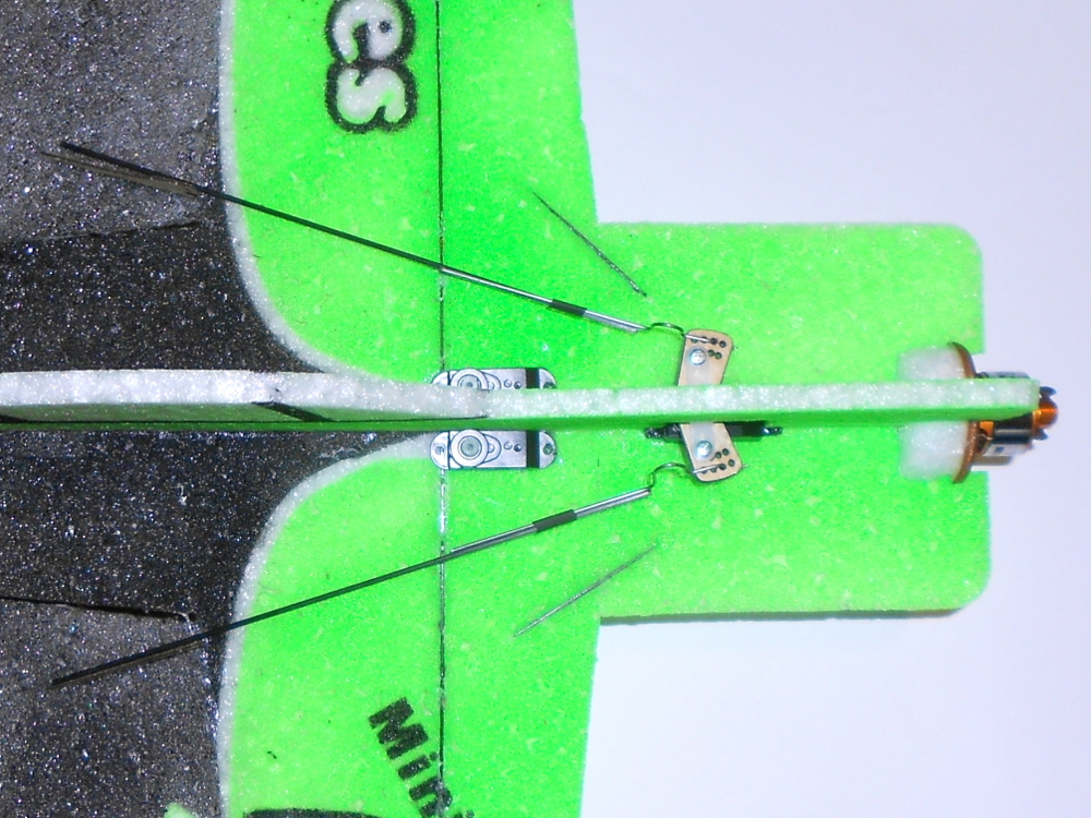
slightly back from the edge of the work surface or table. You want to cut the
foam to a point but not remove any of the top paint surface. Place a cork
backed metal ruler on top of the stabilizer the same distance from the edge as
the thickness of the foam. Using a new X-Acto blade or snap knife, trim along
the edge/ruler at a 45 degree angle the length of the edge. If the foam starts to
drag and rip, change to a new blade. Cut the elevator in the same manner. Cut
bevels in the elevator counterbalances to prevent binding.
Bevel both pieces of all the hinge joints. Lay the
stabilizer top side down (important for painted kits) with the hinge edge
slightly back from the edge of the work surface or table. You want to cut the
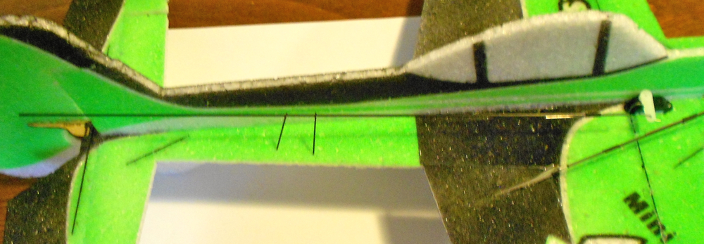
foam to a point but not remove any of the top paint surface. Place a cork
backed metal ruler on top of the stabilizer the same distance from the edge as
the thickness of the foam. Using a new X-Acto blade or snap knife, trim along
the edge/ruler at a 45 degree angle the length of the edge. If the foam starts to
drag and rip, change to a new blade. Cut the elevator in the same manner. Cut
bevels in the elevator counterbalances to prevent binding.
3.
 Continue cutting bevels in the aileron and wing control
surfaces being careful to make left and right ailerons and the matching surface
on the wings. Again, lay the top painted surface on the table through this
process. Do not cut the bevels in the fuselage or rudder at this time.
Continue cutting bevels in the aileron and wing control
surfaces being careful to make left and right ailerons and the matching surface
on the wings. Again, lay the top painted surface on the table through this
process. Do not cut the bevels in the fuselage or rudder at this time.
4.
Our
preferred method of hinging is glue hinges and that is what we will reference
in these instructions. Feel free to substitute your favorite method but you
might want to do a test hinge with some of the EPP scraps in the kit to see the
benefits. Check out this YouTube video to see how easy it is to make the glue
hinge. http://www.youtube.com/watch?v=q0uK8KlR-0I
5.
 Holding the two pieces to be hinged together with the top
paint inward, smear a thin coating of Foam-Tac/UHU/Welders glue on the points
of the bevels you have just cut. Start with the elevator and stabilizer. The
hinge is best when just a fine coating of glue is used and the glue overlaps
the point of the bevel about 1/8” on either side. With the stab and elevator
coated, let them dry to the touch. Place the stab and elevator on the building
surface with the hinge bevel points on the top (top paint up) and slide the two
pieces into contact. “Squish” them together gently, but firmly. Flex the hinge
to make sure it moves freely. This joint will strengthen overnight. Continue with
the hinging of the ailerons.
Holding the two pieces to be hinged together with the top
paint inward, smear a thin coating of Foam-Tac/UHU/Welders glue on the points
of the bevels you have just cut. Start with the elevator and stabilizer. The
hinge is best when just a fine coating of glue is used and the glue overlaps
the point of the bevel about 1/8” on either side. With the stab and elevator
coated, let them dry to the touch. Place the stab and elevator on the building
surface with the hinge bevel points on the top (top paint up) and slide the two
pieces into contact. “Squish” them together gently, but firmly. Flex the hinge
to make sure it moves freely. This joint will strengthen overnight. Continue with
the hinging of the ailerons.
6.
 Once all the elevator and ailerons have been hinged, it is
time to do the main assembly. Working in an area large enough that the entire
outline of the plane can lay flat, take the two wing panels and test fit them
making note of the surfaces that make contact and spread the contact glue on
both sides thinly and let it dry. Slide the wings together top side towards the
table and press firmly together on the flat surface so they align and attach.
Once all the elevator and ailerons have been hinged, it is
time to do the main assembly. Working in an area large enough that the entire
outline of the plane can lay flat, take the two wing panels and test fit them
making note of the surfaces that make contact and spread the contact glue on
both sides thinly and let it dry. Slide the wings together top side towards the
table and press firmly together on the flat surface so they align and attach.
7.
 Insert the carbon fiber strip into the wing slot and while
lightly compressing the foam around the carbon fiber strip, wick CA into the
joint and use kicker to make it seal. Work your way down the joint being
careful to keep the wing flat on the building surface (this is why you protected
it with plastic/wax paper). Once you have applied glue to one side, flip the
wing over and apply glue to the other side also to firmly attach the wing
support.
Insert the carbon fiber strip into the wing slot and while
lightly compressing the foam around the carbon fiber strip, wick CA into the
joint and use kicker to make it seal. Work your way down the joint being
careful to keep the wing flat on the building surface (this is why you protected
it with plastic/wax paper). Once you have applied glue to one side, flip the
wing over and apply glue to the other side also to firmly attach the wing
support.
8.
 Locate the horizontal front (motor mount area) of the
fuselage and fit it to the front of the wing. Spread contact glue on both edges
that come in contact and press in place.
Locate the horizontal front (motor mount area) of the
fuselage and fit it to the front of the wing. Spread contact glue on both edges
that come in contact and press in place.
9.
 Find the pieces for the motor stick mount and glue it into
the forward slot in the horizontal front Fuselage piece.
Find the pieces for the motor stick mount and glue it into
the forward slot in the horizontal front Fuselage piece.
10.
Attach
the rear horizontal fuselage piece to the rear of the wing in the same manner.
11.
 Take the stab/elevator assembly and making note of the
wing hinge line (we consider the side with the smooth joint the top and the
side with the bevel to be the bottom), attach it to the rear fuselage piece in
the same way with the hinge facing the same side as the wing (both up or both
down).
Take the stab/elevator assembly and making note of the
wing hinge line (we consider the side with the smooth joint the top and the
side with the bevel to be the bottom), attach it to the rear fuselage piece in
the same way with the hinge facing the same side as the wing (both up or both
down).
12.
 There is a small piece of flat carbon strip in the kit
which can be optionally used to further reinforce the nose of the plane. Just
cut the carbon in half and cut slices into the nose area as shown and CA in
place.
There is a small piece of flat carbon strip in the kit
which can be optionally used to further reinforce the nose of the plane. Just
cut the carbon in half and cut slices into the nose area as shown and CA in
place.
13.
 Install another piece of carbon across the aileron corner
to prevent ripping in this location.
Install another piece of carbon across the aileron corner
to prevent ripping in this location.
14.
 You should now have an outline of the completed plane.
This is a good place to paint the plane before you attach the fuselage pieces
if you purchased an unpainted kit.
You should now have an outline of the completed plane.
This is a good place to paint the plane before you attach the fuselage pieces
if you purchased an unpainted kit.
15.
 Once your paint is dry, remove the fuselage halves from
the foam sheet and bevel the rudder hinge joint. Check the elevator horn slot
position. You want the point of the rudder hinge bevel on the side opposite the
elevator horn slot. This allows your rudder horn and servo to be on the side
opposite the elevator servo. Make sure that you bevel the same sides of the
rear fuselage and rudder. Do not hinge the rudder at this time.
Once your paint is dry, remove the fuselage halves from
the foam sheet and bevel the rudder hinge joint. Check the elevator horn slot
position. You want the point of the rudder hinge bevel on the side opposite the
elevator horn slot. This allows your rudder horn and servo to be on the side
opposite the elevator servo. Make sure that you bevel the same sides of the
rear fuselage and rudder. Do not hinge the rudder at this time.
16.
 Place the plane outline subassembly with the smooth hinge
joint/top paint surface down on the building surface so the V bevel is facing
up. Find the fuselage bottom and test fit it into the notches on the outline.
Smear glue on the two pieces and attach the fuselage bottom in place making
sure it stands perpendicular to the horizontal surface.
Place the plane outline subassembly with the smooth hinge
joint/top paint surface down on the building surface so the V bevel is facing
up. Find the fuselage bottom and test fit it into the notches on the outline.
Smear glue on the two pieces and attach the fuselage bottom in place making
sure it stands perpendicular to the horizontal surface.
17.
 Find the two thin (3mm) wedge shaped EPP tail stiffeners.
These are glued to the bottom of the fuselage at a 45 degree angle to form a
triangle cross-section with the fuselage bottom and horizontal outline that is
even with the rear fuselage bevel. This will prevent the tail from twisting in
flight, so it is important to complete this step flat on the building board to
maintain the alignment.
Find the two thin (3mm) wedge shaped EPP tail stiffeners.
These are glued to the bottom of the fuselage at a 45 degree angle to form a
triangle cross-section with the fuselage bottom and horizontal outline that is
even with the rear fuselage bevel. This will prevent the tail from twisting in
flight, so it is important to complete this step flat on the building board to
maintain the alignment.
18.
 The large end of the wedge should face the front/wing end.
Dry fit the wedge in place so you have an idea of where the glue should be
spread and attach one of the thin wedge shaped pieces to each side of the rear
fuselage. This is a good place to take a break and let all the glue strengthen.
The large end of the wedge should face the front/wing end.
Dry fit the wedge in place so you have an idea of where the glue should be
spread and attach one of the thin wedge shaped pieces to each side of the rear
fuselage. This is a good place to take a break and let all the glue strengthen.
19.
 Take the plywood aileron servo bellcrank (bowtie shaped)
and glue it to the existing nylon servo arm using CA. Rough the surface of the
nylon servo arm with sandpaper first. Position/align the center hole of the
plywood bellcrank concentric with the screw hole in the nylon servo arm. If you
are using the 9 gram HXT900 servo included in our completer kit you will find alignment
holes in the bellcrank that either the .032” z-bend rods or #1 screws can be
used to align the bellcrank. We have cut the center hole to be snug on the
servo arm and attach under the arm.
Take the plywood aileron servo bellcrank (bowtie shaped)
and glue it to the existing nylon servo arm using CA. Rough the surface of the
nylon servo arm with sandpaper first. Position/align the center hole of the
plywood bellcrank concentric with the screw hole in the nylon servo arm. If you
are using the 9 gram HXT900 servo included in our completer kit you will find alignment
holes in the bellcrank that either the .032” z-bend rods or #1 screws can be
used to align the bellcrank. We have cut the center hole to be snug on the
servo arm and attach under the arm.
20.
 With the aileron servo bellcrank mounted as shown, install
the 9 gram aileron servo in the precut hole
in the front of the plane. Note that the servo output shaft is towards the rear
and the flat side of the bellcrank is also. Tack glue the servo in place with
your preferred method, I use Foam-Tac glue on the mounting ears but other
people use low temperature hot glue.
With the aileron servo bellcrank mounted as shown, install
the 9 gram aileron servo in the precut hole
in the front of the plane. Note that the servo output shaft is towards the rear
and the flat side of the bellcrank is also. Tack glue the servo in place with
your preferred method, I use Foam-Tac glue on the mounting ears but other
people use low temperature hot glue.
21.
 Using a small piece of the flat carbon fiber, cut a slit
in and reinforce the area over the top of the aileron servo cutout in the top
fuselage. Extend the piece beyond the cutout to reinforce it in the case of
hard nose in landings.
Using a small piece of the flat carbon fiber, cut a slit
in and reinforce the area over the top of the aileron servo cutout in the top
fuselage. Extend the piece beyond the cutout to reinforce it in the case of
hard nose in landings.
22.
 Glue the fuselage top onto the plane, aligning it with the
slots. Cut the servo hole out if necessary to allow clearance over the servo
arm. Glue with contact glue.
Glue the fuselage top onto the plane, aligning it with the
slots. Cut the servo hole out if necessary to allow clearance over the servo
arm. Glue with contact glue.
23.
 Insert the aileron control horns into the precut slots in
the top of the ailerons so they are flush with the bottom of the aileron slot
and the holes are aligned over the hinge line. Glue in place with CA along the
entire length. These longer horns provide support to the control surfaces.
Insert the aileron control horns into the precut slots in
the top of the ailerons so they are flush with the bottom of the aileron slot
and the holes are aligned over the hinge line. Glue in place with CA along the
entire length. These longer horns provide support to the control surfaces.
24.
Put
the elevator and rudder servos in the precut servo holes just behind the wing
spar. Glue the servos in place. CA can be used, some people prefer hot glue or
you can use contact glue. You want them firmly attached.
25.
 Find the materials for the
pushrods and bend adjustment angles into half of the z-bend wires. I do these
bends with a set of rounded needle nose pliers but V shaped bends are just as
good. Following this method you will probably never need to do any adjustments
that way.
Find the materials for the
pushrods and bend adjustment angles into half of the z-bend wires. I do these
bends with a set of rounded needle nose pliers but V shaped bends are just as
good. Following this method you will probably never need to do any adjustments
that way.
26.
 Using the heat shrink tubing,
attach the adjustable wires to the 4 carbon fiber pushrods. Do not glue the
wire in place at this time.
Using the heat shrink tubing,
attach the adjustable wires to the 4 carbon fiber pushrods. Do not glue the
wire in place at this time.
27.
 Insert the shorter pushrods into
the anti-differential bellcrank on the aileron servo. Note that the pointed
lobes on the bellcrank face forward. This bellcrank provides a perpendicular
connection from the servo pivot to the control horn giving the same up and down
throw to the ailerons. Without it the angle would cause mechanical
differential. Cut the pushrods 1/4”-1/2” back from the aileron hinge line with
the bellcrank centered.
Insert the shorter pushrods into
the anti-differential bellcrank on the aileron servo. Note that the pointed
lobes on the bellcrank face forward. This bellcrank provides a perpendicular
connection from the servo pivot to the control horn giving the same up and down
throw to the ailerons. Without it the angle would cause mechanical
differential. Cut the pushrods 1/4”-1/2” back from the aileron hinge line with
the bellcrank centered.
28.
 Remove the pushrods from the plane
and use heat shrink tubing to attach two of the remaining straight z-bend wires
to the cut ends. Do not glue the wires in place. This will allow us to do the
fine adjustments of the pushrod lengths. You should end up with pushrods that
look like this.
Remove the pushrods from the plane
and use heat shrink tubing to attach two of the remaining straight z-bend wires
to the cut ends. Do not glue the wires in place. This will allow us to do the
fine adjustments of the pushrod lengths. You should end up with pushrods that
look like this.
29.
 Install the pushrods into the
aileron horns and then with the bellcrank loose, insert the adjustable ends
into the outer hole, second from the front lobes. Pop the bellcrank back onto
the servo and center it and adjust the ailerons so they are level. The
rods/z-bends will slip under the heat shrink tubing to allow this adjustment
but also hold it in place for gluing. With paper towel or plastic under the
pushrods to avoid marring the paint, glue the wires to the carbon fiber rods
with CA to hold this position.
Install the pushrods into the
aileron horns and then with the bellcrank loose, insert the adjustable ends
into the outer hole, second from the front lobes. Pop the bellcrank back onto
the servo and center it and adjust the ailerons so they are level. The
rods/z-bends will slip under the heat shrink tubing to allow this adjustment
but also hold it in place for gluing. With paper towel or plastic under the
pushrods to avoid marring the paint, glue the wires to the carbon fiber rods
with CA to hold this position.
30.
 Hinge the rudder to the rear of the fuselage using a contact
glue hinge as done on the other control surfaces.
Hinge the rudder to the rear of the fuselage using a contact
glue hinge as done on the other control surfaces.
31.
Locate
the elevator horn and glue the horn in place using Foam-Tac or CA so the holes
are aligned over the hinge.
32.
 Glue the rudder horn in place so that it is on the side of
the fuselage opposite the elevator horn.
Glue the rudder horn in place so that it is on the side of
the fuselage opposite the elevator horn.
33.
 Following this same procedure,
create the longer tail pushrods using the remaining pieces. Be sure to put the
pushrod standoffs on the rods before you create the second end.
Following this same procedure,
create the longer tail pushrods using the remaining pieces. Be sure to put the
pushrod standoffs on the rods before you create the second end.
34.
When
the tail pushrods are completed and installed, poke and glue (Foam-Tac) the
standoffs into the foam at 1/3rd distances from the ends. Adjust the
depth of the standoffs to hold the pushrods as straight as possible from end to
end.
35.
 Using the short carbon fiber cutoff pieces from making the
aileron pushrods, cut diagonal slots in the foam between the rear fuselage and
front of the stabilizer long enough to insert these pieces and glue them in
place using CA glue. This helps prevent the stabilizer from skewing with full
elevator deflection.
Using the short carbon fiber cutoff pieces from making the
aileron pushrods, cut diagonal slots in the foam between the rear fuselage and
front of the stabilizer long enough to insert these pieces and glue them in
place using CA glue. This helps prevent the stabilizer from skewing with full
elevator deflection.
36.
 Poke the pushrod standoffs into the foam at 1/3rd
intervals along the pushrod to keep it from flexing in flight and glue to the
foam using CA, being careful not to let it run up the plywood and bond to the
pushrod.
Poke the pushrod standoffs into the foam at 1/3rd
intervals along the pushrod to keep it from flexing in flight and glue to the
foam using CA, being careful not to let it run up the plywood and bond to the
pushrod.
37.
 Install the motor and propeller and position the ESC on
the front of the plane. Position the receiver also.
Install the motor and propeller and position the ESC on
the front of the plane. Position the receiver also.
38.
 The plane is now completely assembled. Route the servo
wires through a slit in the foam to the receiver side of the fuselage and
connect the servos to the receiver and using Velcro, attach the receiver and
ESC to the fuselage. Put a long strip of Velcro on the opposite side below the
wing spar in order be able to move the battery forward and back to fine tune
your balance. The Velcro will stick best to the EPP if you rub some contact
glue on the area you are attaching it to.
The plane is now completely assembled. Route the servo
wires through a slit in the foam to the receiver side of the fuselage and
connect the servos to the receiver and using Velcro, attach the receiver and
ESC to the fuselage. Put a long strip of Velcro on the opposite side below the
wing spar in order be able to move the battery forward and back to fine tune
your balance. The Velcro will stick best to the EPP if you rub some contact
glue on the area you are attaching it to.
39.
Use
tie wraps to gather the wires in a neat bundle.
40.
The
CG of the plane is on the carbon wing spar to 1/4” behind it.
41.
Control
throws are a matter of personal preference. Some people want lots of surface
movement to do 3D maneuvers while other people like a more docile handling
plane. You can add exponential to your controls to calm down the center portion
of the travel. EPP is very durable and also easily repaired. Don’t be afraid to
challenge yourself and learn new things. Get out and enjoy flying.
Copyright 2011-2017 RA Cores,
Southbridge MA - All rights reserved